Answer the question
In order to leave comments, you need to log in
How to understand transfer characteristics?
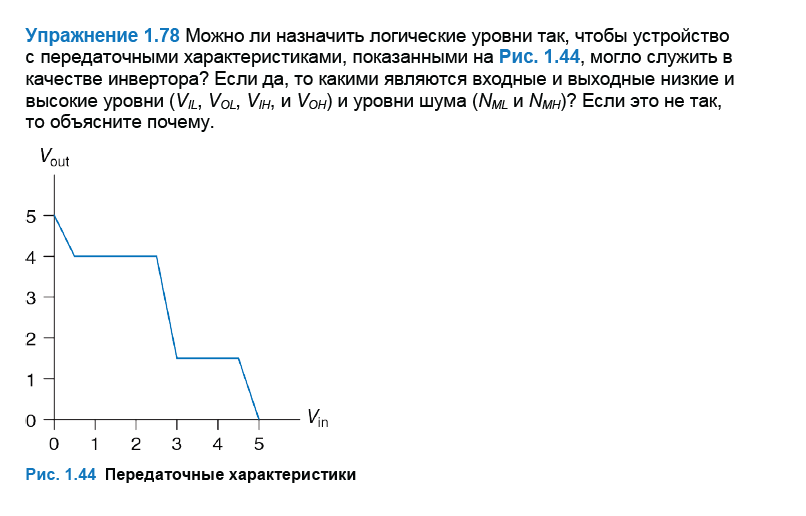
Please tell me how to deal with the problem described in the screenshot. This is a task at the end of the chapter in the textbook, but the part about transfer characteristics is literally in a nutshell, as a result, there was a difficulty in understanding what they want and how to answer this question in detail. I would like to figure out what's what.
1. Is it possible or not?
2. What do you mean ...could serve as an inverter?
3. How to determine the entry and exit levels based on the chart
Answer the question
In order to leave comments, you need to log in
1. You can.
2. Here it is necessary to build on the definition of an inverter. In logic circuits, an inverter is an element that "flips" the signal applied to it. Log.1 was applied to the input - log.0 appeared at the output. Filed 0 - output 1. The inverter is included as the main part of almost any log. element in any digital logic series. For example, a non-inverting signal repeater is usually two inverters connected in series.
3. To determine them, you need to set the threshold zone - the value of the input / output voltages, below and above which the signal will certainly be attributed to log.0 or 1. Inside this zone, of course, there will be uncertainty, and if there is a noise signal in this zone , then at the output we get the devil knows what, but outside of it everything should be clear. This picture illustrates it well:
On the left there is a narrow threshold zone (yes, there is practically none there, there is only a single threshold level), and therefore the noise jumps to the output, on the right it is quite wide, and this allows you to filter out the noise superimposed on the input signal.
Now we can look at your schedule. It is clearly seen that 2.7 volts is a convenient threshold level, and a linear section in the middle, limited by horizontal sections, allows it to be extended to the zone. These horizontal ones do not give anything in the sense of filtering noise - therefore, the threshold zone according to your drawing can be selected within 2.3 ... 3 volts (to guarantee noise immunity - even wider, but other nuances begin to matter there). To this we can add that the threshold zone in the transfer characteristic of the logic element should be as steep as possible so that the signal jumps it as quickly as possible - the inclined section in the center of the picture also fits this criterion best. Why is it important? Yes, because in this zone the logic element turns from digital to analog, becoming an amplifier, and the slope of this section is actually the gain. And the amplifier, instead of filtering noise, will, on the contrary, contribute to their propagation. Ideally, the logic element for suppressing the gain effect should also contain a Schmitt trigger, the thresholds of which should be set to the same 2.3 and 3 (or more) volts.
Didn't find what you were looking for?
Ask your questionAsk a Question
731 491 924 answers to any question