Answer the question
In order to leave comments, you need to log in
Why does the ADC return a sine wave?
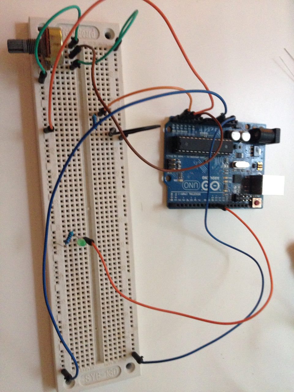
Very strange ADC behavior. The task is to read the readings of several potentiometers and send them to another board (FPGA). I started by repeating the example www.arduino.cc/en/Tutorial/AnalogInOutSerial
However, difficulties arose - the diode blinks all the time at a frequency of about 3Hz, just like the values changing from zero to 1023 and back come to the serial port
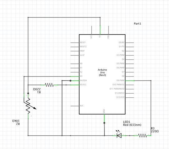
const int analogInPin = A4;  // Analog input pin that the potentiometer is attached to
const int analogOutPin = 9; // Analog output pin that the LED is attached to

int sensorValue = 0;        // value read from the pot
int outputValue = 0;        // value output to the PWM (analog out)

int a2 = 0;
int a3 = 0;
int a4 = 0;
int a5 = 0;

void setup() {
  // initialize serial communications at 9600 bps:
  Serial.begin(9600);
}

void loop() {

  // read the analog in value:
  sensorValue = analogRead(A1);
  a2 = analogRead(A2);
  a3 = analogRead(A3);
  a4 = analogRead(A4);
  a5 = analogRead(A5);

  outputValue = map(sensorValue, 0, 1023, 0, 255);
  analogWrite(analogOutPin, outputValue);

  // print the results to the serial monitor:
  Serial.print("a2 = " );
  Serial.print(a2);
  Serial.print("\t a3 = ");
  Serial.print(a3);
  Serial.print("\t a4 = ");
  Serial.print(a4);
  Serial.print("\t a5 = ");
  Serial.println(a5);

  delay(100);
}a2 = 160. a3 = 0. a4 = 0. a5 = 0
a2 = 92. a3 = 0. a4 = 0. a5 = 0
a2 = 64. a3 = 0. a4 = 0. a5 = 0
a2 = 55. a3 = 0. a4 = 0. a5 = 0
a2 = 90. a3 = 75. a4 = 90. a5 = 99
a2 = 207. a3 = 340. a4 = 381. a5 = 425
a2 = 550. a3 = 934. a4 = 983. a5 = 1023
a2 = 766. a3 = 1023. a4 = 1023. a5 = 1023
a2 = 877. a3 = 1023. a4 = 1023. a5 = 1023
a2 = 928. a3 = 1023. a4 = 1023. a5 = 1023
a2 = 919. a3 = 953. a4 = 935. a5 = 920
a2 = 797. a3 = 696. a4 = 665. a5 = 631
a2 = 490. a3 = 179. a4 = 132. a5 = 85
a2 = 247. a3 = 6. a4 = 0. a5 = 0
a2 = 135. a3 = 0. a4 = 0. a5 = 0
a2 = 84. a3 = 0. a4 = 0. a5 = 0
a2 = 63. a3 = 0. a4 = 0. a5 = 0
a2 = 59. a3 = 0. a4 = 9. a5 = 25
a2 = 114. a3 = 129. a4 = 143. a5 = 158
a2 = 306. a3 = 519. a4 = 564. a5 = 610
a2 = 664. a3 = 1001. a4 = 1023. a5 = 1023
a2 = 823. a3 = 1023. a4 = 1023. a5 = 1023
a2 = 904. a3 = 1023. a4 = 1023. a5 = 1023
a2 = 936. a3 = 1023. a4 = 1023. a5 = 1023
a2 = 884. a3 = 874. a4 = 854. a5 = 834
a2 = 727. a3 = 560. a4 = 539. a5 = 498
a2 = 406. a3 = 74. a4 = 33. a5 = 0
a2 = 212. a3 = 0. a4 = 0. a5 = 0
a2 = 120. a3 = 0. a4 = 0. a5 = 0
a2 = 79. a3 = 0. a4 = 0. a5 = 0
a2 = 68. a3 = 0. a4 = 0. a5 = 0Answer the question
In order to leave comments, you need to log in
By
One point there are two analog inputs (A0 and A1, although for testing you can plug all of them into one point for measurement, where the blue wire is painted on the potentiometer) and see what they read. If one jumps while the others are calm, then it is better not to use an inadequate analog input.
Ideally, all should show the same value.
I need a connection diagram
about noise on the ADC, these are ordinary pickups, this is normal if there is no pull-up
Didn't find what you were looking for?
Ask your questionAsk a Question
731 491 924 answers to any question