Answer the question
In order to leave comments, you need to log in
Flickering LCD SBLCDA4 on MSP430?
As their subject is already clear, I have some problems with setting up the display on the MSP430. This display, SBLCDA4, is used in the MSP-EXP430FG4618 development board , though I have an MSP430F4784 MK. 
It was exactly according to the scheme of this debug board that I assembled the scheme for my project, but, unfortunately, the display flickers quite noticeably: to understand this, it was necessary to order boards as soon as possible. And here they come, but the problem is not corrected. I tried a lot of firmware, and of course, examples from TI prepared exactly for this display.
This code would have to light up all segments of the display:
#include "msp430.h"
void main(void)
{
int i;
WDTCTL = WDTPW + WDTHOLD;
FLL_CTL0 |= XCAP10PF;
LCDACTL = LCDON + LCD4MUX + LCDFREQ_128;
LCDAPCTL0 = LCDS0+LCDS4+LCDS8+LCDS12+LCDS16+LCDS20;
P5SEL = BIT2+BIT3+BIT4;
for( i = 0; i < 11; i ++)
{
         LCDMEM[i] = 0xFF;
}

_BIS_SR(LPM3_bits);
}


Answer the question
In order to leave comments, you need to log in
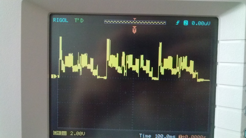
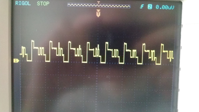
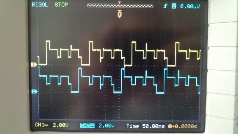
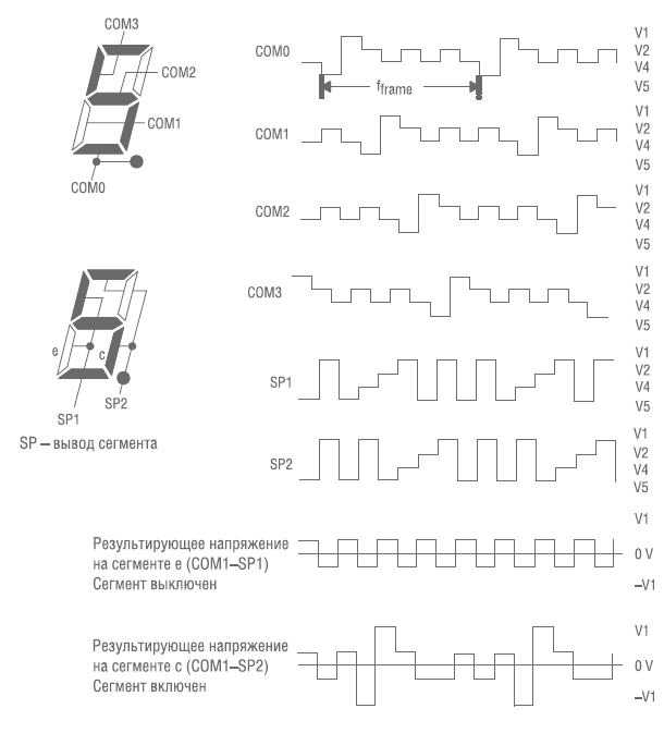
I may not understand something, but com0 is sort of like a digital select signal and should be either zero or one. You have at least 4 different levels on it (very beautiful, which is strange). Maybe this is where we should start. Although I can be wrong, because. I have never worked with such indicators, and some kind of datasheet is completely useless ...
Never encountered.
Perhaps a stupid assumption...
But judging by this
Board.h:
#define LCD_TEST 1 // Set to 1 to include LCD test functions
and this LCD.h
#if LCD_TEST > 0

extern void testAll(void);
extern void testSymbol(void);
extern void testArrow(void);
extern void testFunc(void);
extern void testBatt(void);
extern void testSigLvl(void);
extern void testPwrLvl(void);
extern void testSpecialChar(void);
extern void testChar(void);

#endif // LCD_TEST
By default, it looks like a test is started there, which blinks all the elements of the indicator.
And I see something very similar in the video ...
No? LCD_TEST to zero?
Didn't find what you were looking for?
Ask your questionAsk a Question
731 491 924 answers to any question