Answer the question
In order to leave comments, you need to log in
Why resistors for a seven-segment indicator?
I have such a decoder for a seven-segment indicator tec.org.ru/board/127-1-0-470 and something like this indicator ocenil.ru/photos/semisegmentnyy-indikator-kitay-se... - display) 10 legs.
I don’t understand
1) why connect each leg through a resistor at all, isn’t it easier to connect everything directly and work at lower voltages?
2) how to find out what resistors are needed?
3) From what minimum voltages will the indicator start?
Answer the question
In order to leave comments, you need to log in
Diode indicator. The diode is ignited not by voltage, but by current. It is very difficult to choose the voltage so that the current does not exceed. The difference is in fractions of a volt.
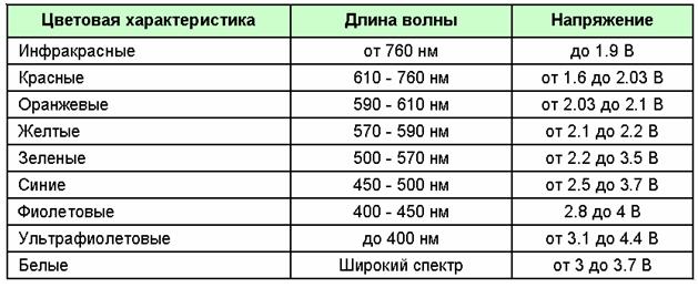
The minimum voltage at which the indicator will start depends on the color. It should not be lower than the voltage drop of the LED.
Look here.
The resistor is considered simple. We take the supply voltage, subtract the LED drop voltage from it. We get the operating voltage U. Now we need to choose such a resistor so that, according to Ohm's law (U \u003d I * R), the current does not exceed the maximum allowable for this LED. For a regular indicator LED (not super bright), the current is usually 0.010A or even 0.005A
1) so as not to burn the diodes.
2) look at the characteristics of the indicator diodes and calculate a little
3) see point two, or in practice try to turn it on with a rheostat and a voltmeter
, here's info for thought: www.avprog.narod.ru/student/ph/ph_iii_203_01.htm
1) There may be a short circuit + the output current of the mikruhi is limited.
2) U/I if to ground.
3) We need a minimum current, any voltage within reason.
You can really get away from these resistors. At one time, we made a voltage stabilizer and fed all segments of 3 indicators (i.e., a total of 24 diodes) with it, in principle, the whole thing worked. But the solution with resistors is simpler and more versatile, in addition, it takes into account such a moment: if you stupidly connect everything in parallel and power it with the same current, some segments may glow brighter than others due to the factory variation in the characteristics of the diodes themselves.
Well, just connecting everything in parallel and feeding through one resistor will not work either: the more segments are lit, the more the overall brightness of the indicator will fall, in short, it will be nonsense in general. :)
In other words, this path has already been passed, the experiment can not be repeated. We had a small-scale production and had to put a potentiometer on the voltage regulator to adjust the brightness of each individual instance of the device.
In general, it's not worth it. :)
Didn't find what you were looking for?
Ask your questionAsk a Question
731 491 924 answers to any question