Answer the question
In order to leave comments, you need to log in
Where is the error in connecting the LED panel?
RGB ice panel 32 by 16, marking p10smd180920-719j/h10000 P10-4S 32*16
Connected according to the scheme https://learn.adafruit.com/32x16-32x32-rgb-led-matrix. The sketch is from the same place, from amps and others from the Internet.
For some reason, the blue and red lights are wrong. When filled with blue, half of the pixels are red, when filled with red, half are blue. White or green - everything is correct.
When drawing shapes or text, everything is drawn incorrectly. For example, instead of this picture 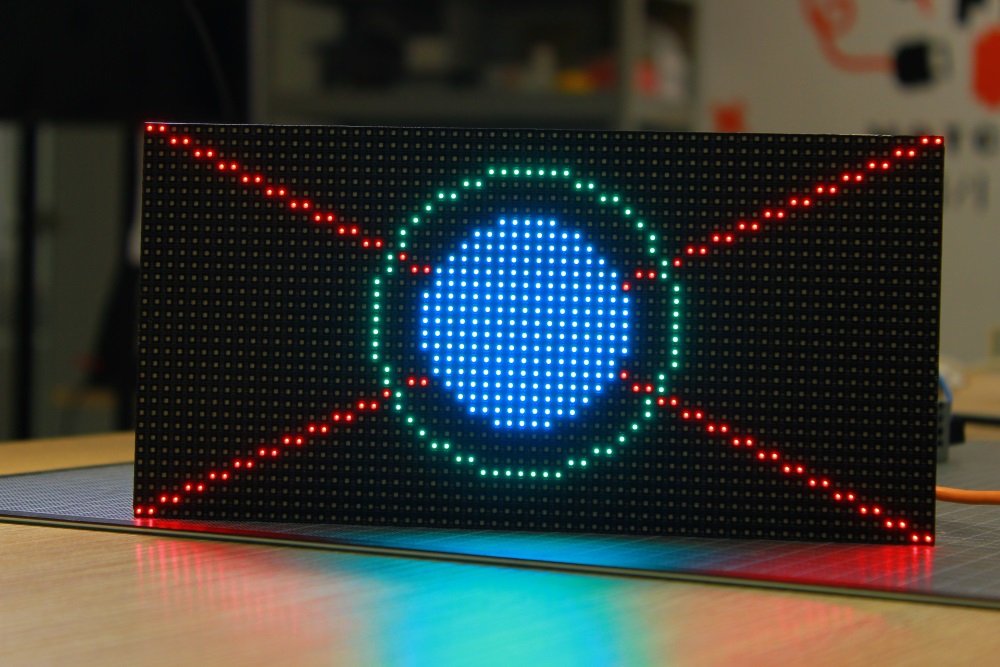
, it turns out like this 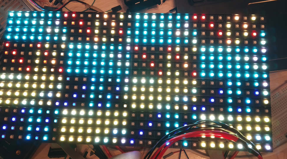
. I tried 6 different panels, arduino too. The panel is powered properly from the PSU 5V 40A, does not sag.
Help with advice, what could be the problem?
Answer the question
In order to leave comments, you need to log in
fragment addressing is obviously mixed up.
the photo shows the right lines, but they are in the wrong places.
most likely your panel has some other addressing, different from the one used in the sketches.
perhaps the data format is different, or a different number of bits,
study the sketches and compare with the datasheet for the panel.
Output one point at a time or one line, and see what goes where. So you can understand the pattern and remake the library, or write wrappers for its functions
Didn't find what you were looking for?
Ask your questionAsk a Question
731 491 924 answers to any question