Answer the question
In order to leave comments, you need to log in
Optocoupler diode resistance - how to find out?
In the circuit, the voltage is removed from the divider and goes through the filter to the optocoupler diode. As I understand it, the trimmer equalizes the ratio of the divider arms, and also limits the diode current. In order to test only with the A2 block in real life, I most likely need to know the resistance of the diode. 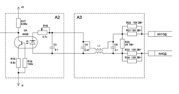
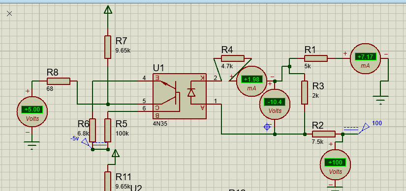
By the way, can you explain why the circuit in the proteus does not work?
Answer the question
In order to leave comments, you need to log in
In fact, an open diode has no resistance and the current through it is determined exclusively by a ballast resistor
. Well, if you really want to, you can determine according to Ohm's law by dividing the drop voltage by the current flowing. The voltage on the open LED will always be the same 0.8-2.5V, depending on the manufacturing technology
In the "prosthetic" circuit, the voltage at the output of the optocoupler is measured relative to the moon (the common wire of the input part of the circuit), and not the earth (the common wire of the output part of the circuit).
LED resistance... can be estimated from fig. 1 in this document: https://www.vishay.com/doc?81181
voltage drop 0.6-0.75
why do you need to know exactly?
this plays a role at high currents and the initial frequency (but in feeders it is about 80-120khz
at a higher frequency, feeders are not built,
I don’t know (I’m not a designer / developer,
I’m the one who repairs this crap)))
current 1 mA = I don’t think that more) you can google the datasheet
i never used it = no need
Didn't find what you were looking for?
Ask your questionAsk a Question
731 491 924 answers to any question