Answer the question
In order to leave comments, you need to log in
msp430 internal op amp?
Good afternoon!
I need to connect a microphone to msp430.
I did the following: 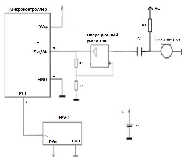
But now you need to use the "operational amplifier from the microcontroller". Please tell me: what does this mean and how to do it?
Answer the question
In order to leave comments, you need to log in
MSP430F2xx series
Similar to 1xx generation, but running at lower power, support up to 16MHz operation. Device Parameters:
.....
Other Integrated Peripherals: Operational Amplifiers , .....
a couple of google requests
www.ti.com/lit/ug/tidu443/tidu443.pdf
MSP430F2274 Transimpedance Amplifier (TIDM-TIA) User's Guide
an example of an applied circuit using an integrated amplifier.
www.ti.com/lit/ug/slau144j/slau144j.pdf - microcontroller datasheet.
screenshot of the operational amplifier module.
But now you need to use the "operational amplifier from the microcontroller".
Please tell me: what does this mean and how to do it?
Didn't find what you were looking for?
Ask your questionAsk a Question
731 491 924 answers to any question