Answer the question
In order to leave comments, you need to log in
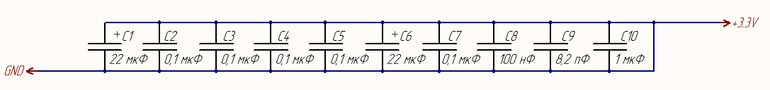
How to place decoupling capacitors? What to fix?
According to
the datasheet on the MK: capacitors C1-C7,
the datasheet for the sensor: capacitors C8,
the datasheet for the radio module: capacitors C9, C10.
As you can see, I just placed them in parallel one after the other. Is it correct? If not, how to do it right?
Thank you for your attention.
Answer the question
In order to leave comments, you need to log in
border-style is none by default, so it's not taken into account
The electrical circuit diagram does not contain information about how the components are located on the board - so it does not matter how you painted them.
It is important that on the wiring diagram / board layout, the capacitors were placed as close as possible to the microcircuit pins - when mounting the pins, it is advisable to solder them directly to the power pins.
Didn't find what you were looking for?
Ask your questionAsk a Question
731 491 924 answers to any question