Answer the question
In order to leave comments, you need to log in
How to debug the device?
Good afternoon. I need to develop a device that emits a square wave whose frequency depends on the amount of light falling on it. I spent a long time with the circuit and layout of the board, just in case I modeled the part in the SPICE simulator, but something went wrong and nothing works.
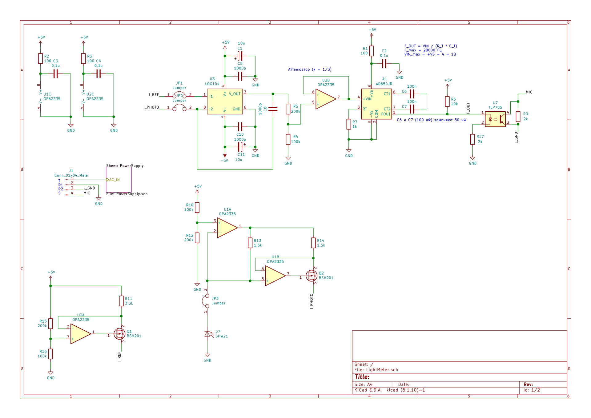
For example, on the second leg of the first operational amplifier, to which the photodiode is connected, there should be 3-3.3 V, but in reality about 1-2.
I perfectly understand that the question is abstract and telepaths are on vacation, but I am at a dead end. At least in general terms, in which direction should you dig? You just don’t want to give up after all the effort, time and resources invested.
Answer the question
In order to leave comments, you need to log in
Why such wild overengineering (U1A, U1B) if LOG104 natively works with photodiodes in photodiode mode? See figures 1 and 9 in its documentation.
Why useless U2B attenuator? You just need to choose according to the formulas so that the calculated photocurrent levels give levels at the output of U3 that are included in the operating range of the VLF U4.
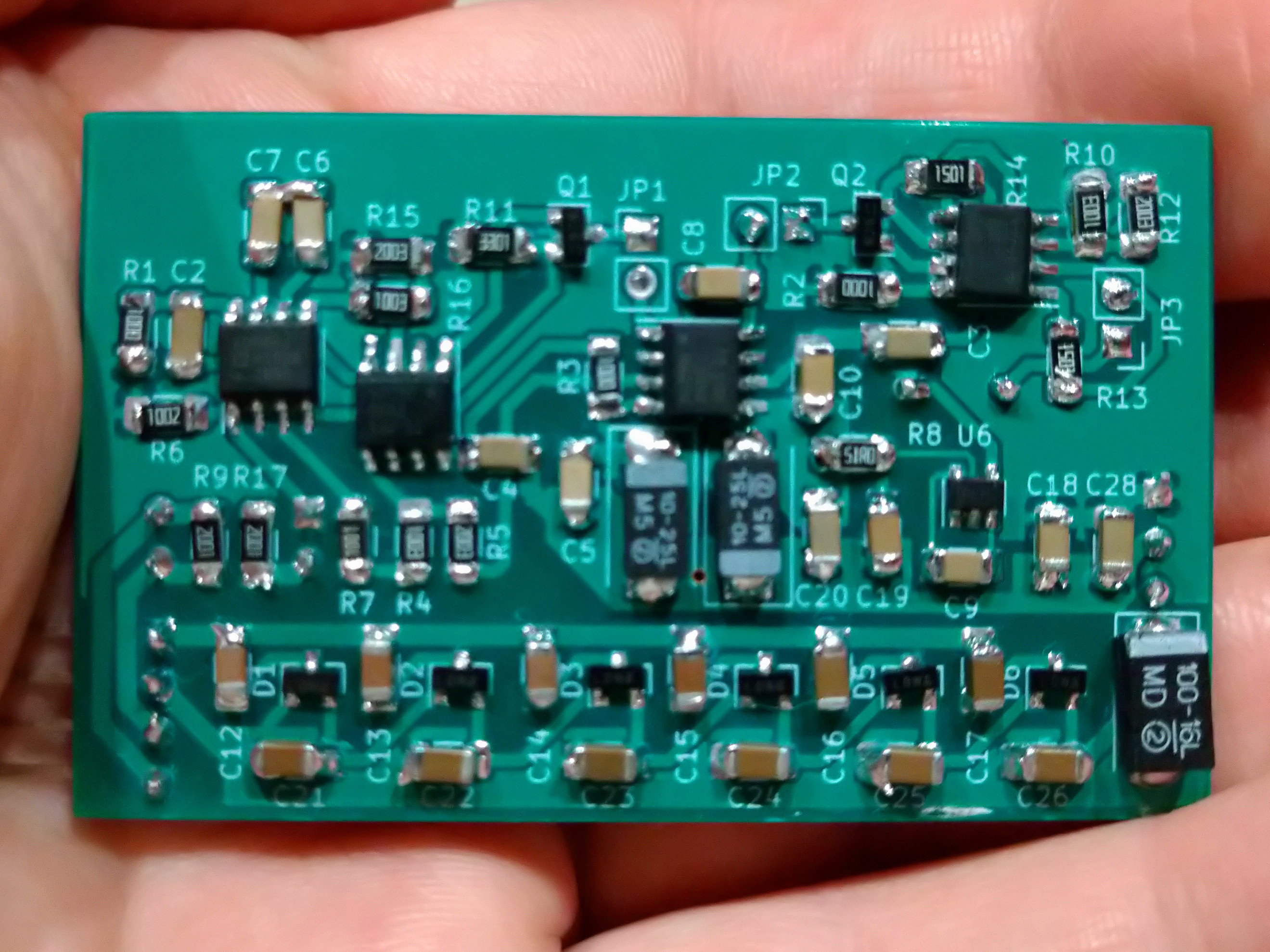
C6-C7 - with which dielectric? Ain't shit like Y5V/Z5U? I would put a film one or, at worst, reduce the capacity by a proportional increase in R7 and take C0G / NP0.
Well, they have already said about the error in the polarity of the photodiode.
PS Judging by the "ladder" of multipliers - will you torture APD with a scintillator?
1. There are only two modes of operation of the LED: generator (direct switching on, and the diode generates electricity, i.e. it is a small solar cell) and diode (locking switching on, and the reverse current of the diode depends on the light intensity). In your case, diode mode is used. But if the diode is reversed, it becomes a generator, and this is very similar to what you have.
2. Take a closer look at the first op. When a modern op-amp is in linear mode, the voltage between its differential inputs is microvolts. This means that if there are 3.2 volts at one input, then the other should have almost the same amount. If the voltages there are very different, then the output will go into saturation (almost plus or almost minus the supply, depending on the polarity at the inputs) and will stop responding to the state of the inputs. So check what's being output at that moment.
Maybe, of course, the advice is stupid, but if 1-2 volts are kept on the leg, is the photodiode plugged in correctly? If it is included in the return line, then it will just fall.
The input voltage can be lower in two cases.
The first one I have already said is that the diode is not connected there.
The second - the OU went into the current limit. But this is unlikely, because even if you short it through 1.5 kΩ to ground, there will be only about 3 mA of output current, and this op-amp has a 50 mA limit.
Of course, there may be an inconspicuous snot hanging somewhere, which is shortening the exit.
What is the voltage at the output of U1A?
By the way, why do you need a current-voltage-current converter in this case?
Wouldn't it be easier to hook up the photodiode to the LOG104 input right away?
Didn't find what you were looking for?
Ask your questionAsk a Question
731 491 924 answers to any question