Answer the question
In order to leave comments, you need to log in
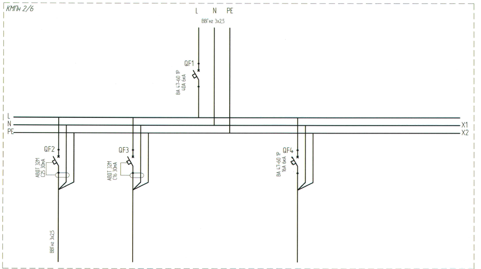
How is the installation in the switchboard according to scheme e4 carried out?
How is the installation done here?
x1, x2 - tires. QF switches.
1. tires, switches are installed in the KMP.
2. L, N, PE are incoming wires? then N and PE are put in the tires, but where does the phase L go? In general, please help. What technology is here?

Answer the question
In order to leave comments, you need to log in
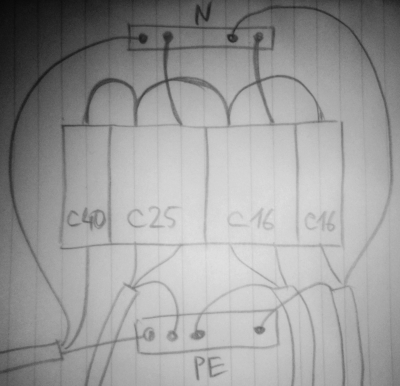
The PE busbar is without options a busbar with wire bolts.
The N bus can be the same as the PE bus, with the switch inputs connected to the bus by wires.
But there is a better option - to take a two-pole comb bus, it will be an N bus and an L bus at once, the shield with the comb looks neater. The excess length of the comb is cut off.
If the installation is without a comb, then you can use a stranded wire and NShVI lugs for installation.
It is bad that in the diagram the introductory switch is single-pole, it is better to replace it with a two-pole one. If QF4 goes to lighting (otherwise why is it not a differential automatic, like the other two?), then 16A is bold, it is better to put 10A.
Upd.:

Formulate a task. What is needed?
What is E4? KMP?
Are you collecting a shield?
The shield includes one three-wire cable and includes three.
One common introductory and each line is protected by a difavtomat.
For zero and phase tires are not needed.
But for the earth - it is necessary.
Oh, and don't forget the colors. Blue - zero, Yellow-green - earth. Color - phase.
Didn't find what you were looking for?
Ask your questionAsk a Question
731 491 924 answers to any question