Answer the question
In order to leave comments, you need to log in
Why is the relay active (green on) when the output is low and vice versa?
I broke my head, I can not understand why this is happening. I make a time relay, set the conditions for switching on and off the relay in time, I display the status of the output for control on the display and I see that when the output is active (ON), the relay seems to work in the reverse mode - the LED is off. At zero at the output, the relay is active. How so?
I'm doing a sketch in FLProg. Of course, you can simply invert the output to the relay and then everything works as it should. But I want to understand why this is happening.
FLProg schema: 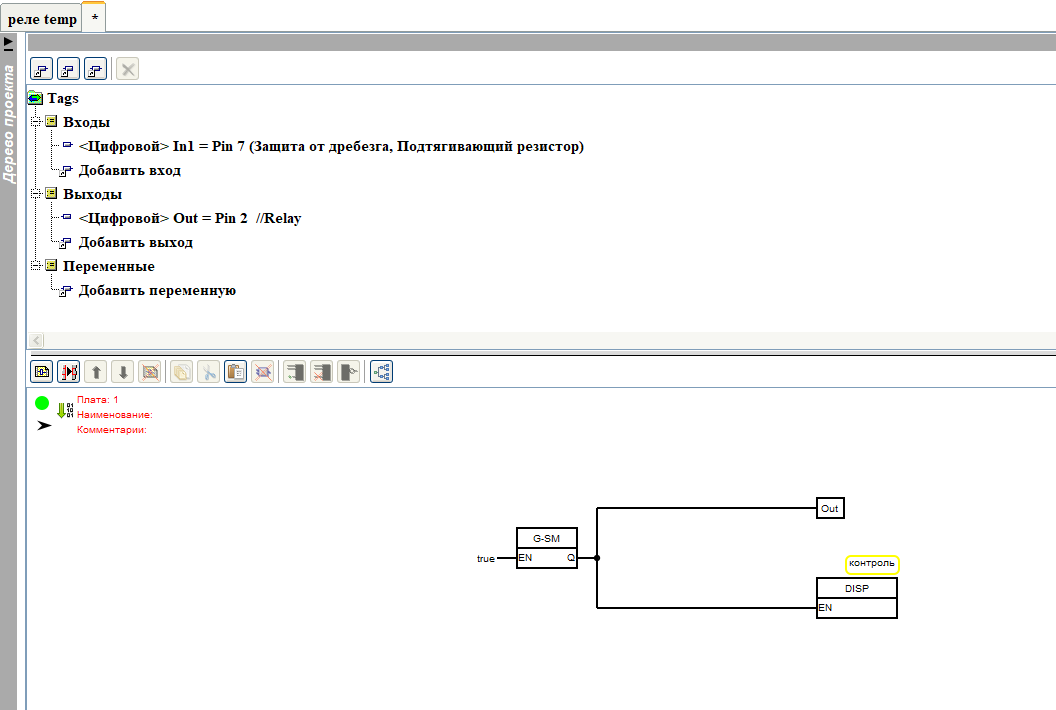
Sketch compiled from this schema:
#include <Wire.h>
#include <LiquidCrystal_I2C.h>
LiquidCrystal_I2C _lcd1(0x27, 16, 2);
int _dispTempLength1 = 0;
boolean _isNeedClearDisp1;

int _disp2oldLength = 0;
bool _gen1I = 0;
bool _gen1O = 0;
unsigned long _gen1P = 0UL;
void setup()
{
  Wire.begin();
  delay(10);
  pinMode(2, OUTPUT);

  _lcd1.init();
  _lcd1.backlight();
}
void loop()
{ if (_isNeedClearDisp1) {
    _lcd1.clear();
    _isNeedClearDisp1 = 0;
  }


  //Плата:1
  if (1) {
    if (! _gen1I) {
      _gen1I = 1;
      _gen1O = 1;
      _gen1P = millis();
    }
  } else {
    _gen1I = 0 ;
    _gen1O = 0;
  }
  if (_gen1I) {
    if ( _isTimer ( _gen1P , 1000 )) {
      _gen1P = millis();
      _gen1O = ! _gen1O;
    }
  }
  digitalWrite(2, _gen1O);
  if (_gen1O) {
    _dispTempLength1 = (String("ON")).length();
    if (_disp2oldLength > _dispTempLength1) {
      _isNeedClearDisp1 = 1;
    }
    _disp2oldLength = _dispTempLength1;
    _lcd1.setCursor(6, 1);
    _lcd1.print(String("ON"));
  } else {
    if (_disp2oldLength > 0) {
      _isNeedClearDisp1 = 1;
      _disp2oldLength = 0;
    }
  }


}
bool _isTimer(unsigned long startTime, unsigned long period )
{
  unsigned long currentTime;
  currentTime = millis();
  if (currentTime >= startTime) {
    return (currentTime >= (startTime + period));
  } else {
    return (currentTime >= (4294967295 - startTime + period));
  }
}Answer the question
In order to leave comments, you need to log in
Usually the relay has a changeover contact, while it is closed with one contact, it is open with the other, when voltage is applied to the relay, the relay is activated, the changeover contact opens with the first but closes with the second.
Therefore, it is important to select the correct contacts for controlled relays.
The second point is the relay control circuit, if one contact of the relay control coil is connected to the positive, then the relay will operate when 0 is applied to the relay.
In general, you should refer to the documentation and figure out according to the scheme what is connected where.
Perhaps there are several options for the operation of the relay which are set by jumpers and the selection of the desired contacts.
In the worst case, this is a Chinese board with a relay and everything works there as the gloomy Chinese genius decided, then you have to fix the program.
It's okay, it happens.
And what, turn on at 1 and turn off at 0 necessarily?
Didn't find what you were looking for?
Ask your questionAsk a Question
731 491 924 answers to any question