Answer the question
In order to leave comments, you need to log in
What does the radiation pattern of such a microwave antenna look like on the board?
Dear radio operators, signalmen, graduates of radio departments, I greet you!
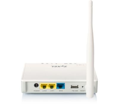
There is such a device Zyxel Keenetic 4G (home Wi-Fi router, model 2011). The device is quite old, but moderately smart and advanced, and most importantly: the software is updated and supports almost all high-speed LTE subscriber terminals of the latest models. Powered by 12V, you can buy for pennies, an excellent consumable for summer cottages with thunderstorms and poor power supply. It was produced in two editions: Revision A and Revision B. The latter is just different in that the external Wi-Fi whip antenna (2.4GHz, KU 5dbi) is supplemented with an internal one (in the photo below it is supposedly, but I'm not a specialist).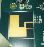
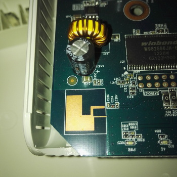
The diagonal of the white "silk-screen" rectangle around the copper is a little less than an inch. It is located in the most empty and farthest corner from the external whip antenna Wi-Fi 2.4GHz 5dbi. There is nothing special on the back of the board.
Added internal Wi-Fi antenna. Now the device uses both external and internal antennas (Diversity technology). The internal antenna does not increase the coverage area, but provides additional sensitivity, increases the reliability of communication when working with a wireless access point and is designed to deal with "dead zones" of reception.
Answer the question
In order to leave comments, you need to log in
If the found rectangular structures on the board still have a second antennaOf course, it's her.
1) Where does it shine? "Dumbbells" perpendicular to the plane of the board? It would be logical to cover the blind "poles" of the whip antenna, especially in a private house with three floors and a basement ...Since its shape is not regular, but is a set of conductors of arbitrary length and width, it is hardly possible to accurately estimate its DN "by eye". I don't think any math can do it. Well, for starters, as a first approximation, consider it spherical. At the same time, it will fill the pauses of the pin at any inclination of the pin.
2) In what range are the KU of such antennas usually located on the board? I'm guessing it's very small.You guess correctly. It is unlikely that there is even 5 dB there.
3) If you unscrew the external whip antenna at 5dBi and screw on the "whip" at 8-10dBi, will the electronics on the board not get sick from such mockery?Absolutely not sick, I have done this more than once. It is only necessary to match the antenna with the 50 ohm cable as accurately as possible in order to prevent standing waves. Well, position the new pin in such a way as to make the most efficient use of its pancake-shaped DN, and in those directions where it has dips, rely on a weak built-in one.
as said, this is the second antenna for Diversity, it does not increase the coverage area. what is Diversity can be read in Google.
If you need to increase the coverage area, then you need to change the antenna.
electronics on the board will not be anything.
Didn't find what you were looking for?
Ask your questionAsk a Question
731 491 924 answers to any question