Answer the question
In order to leave comments, you need to log in
Powerful MOSFET - do I understand correctly that the control parameters are suitable?
Good afternoon!
I immediately apologize and ask you not to send it to more specialized forums, because I only hear that "read literature", but there is no one to ask about the correctness or incorrectness of what is understood from this literature.
So, you need to use Arduino to control a powerful MOSFET transistor (in my case, IRFP250N).
Datasheet for it: https://www.infineon.com/dgdl/irfp250n.pdf?fileId=...
The control is planned to be PWM (PWM), frequency 1kHz. The ambient temperature is 20-40 degrees.
So, there was some misunderstanding of the characteristics of " Gate Threshold Voltage " (2-4 Volts).
as I understand it, this is the threshold after which the transistor is guaranteed to open?
since the Arduino outputs 5 volts, and the PWM frequency is 1 kHz, will the transistor have time to open?
Or all the same, from 5 volts it will not open completely and will warm up (it will be 12 volts, 6 amperes)?
I am also interested in how to understand and where to look in order to find out that the PWM frequency of 1 kHz is within the permissible range (I roughly assume that this is due to the gate capacitance)?
Answer the question
In order to leave comments, you need to log in
guaranteed to open

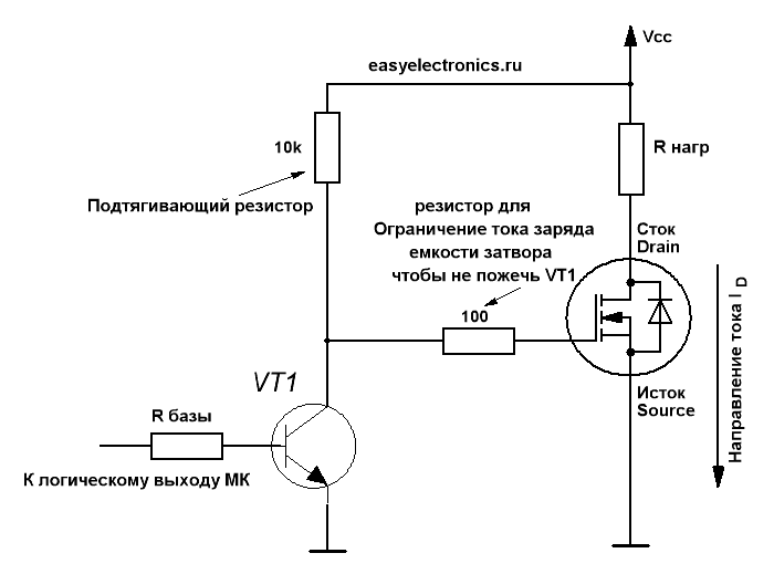
Gate Threshold Voltage is the voltage at which the opening of the transistor channel just BEGINS. It will be fully open at a much higher voltage, usually 15V. If a large current is expected through the transistor, a driver must be installed, otherwise the transistor will not open completely, the channel will have high resistance and the transistor may overheat.
Yes, Gate Threshold Voltage is the threshold voltage after which the transistor will open completely, for this, a voltage between 4 and 20 volts must be applied to the gate (G) of the transistor. Better - closer to the middle.
Since this is an N-channel transistor, it is controlled by a negative voltage, i.e. the voltage on leg G relative to leg S should be from -4V to -20V.
Here for clarity: https://youtu.be/S1UtbfI20OY
Frequency 1kHz - normal. The actual switching speed depends on the resistance on the gate drive line. But it is not necessary to greatly reduce this resistance, because this leads to an increase in the peak current through the Arduino output key when charging the capacitance in the MOSFET (as stated in the video). We can also get closer to the Peak Diode Recovery parameter (maximum voltage slew rate) - but do we need it ?! )
It would be more correct to control through an optocoupler in order to separate the control circuits and power circuits. Or at least through an intermediate control transitor, opamp, key-assembly (ULN2003A), MOSFET driver
Didn't find what you were looking for?
Ask your questionAsk a Question
731 491 924 answers to any question