Answer the question
In order to leave comments, you need to log in
Mikrotik + DHCP + DHCP relay + 2 VLANs, how to implement?
Colleagues, good afternoon.
I want to implement video surveillance and a WI-FI network in separate VLANs on Mikrotik.
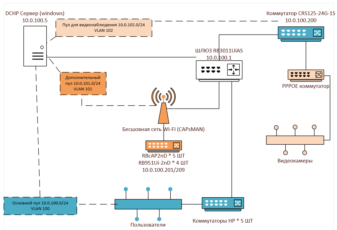
Approximate network diagram: 
Now 1 network 10.0.100.0/24 is involved (DHCP is distributed on a Windows server) with CAPsMAN raised on the gateway, a possible future VLAN 100 (is it also worth driving the main network into a VLAN?)
It is planned to use 2 more, on which I wanted I would like to separate traffic, but leave access from 1 to another:
2 network for WI-FI devices 10.0.101.0/24 I wanted to add to VLAN 101
3 network for video surveillance 10.0.102.0/24, respectively, in VLAN 102
I
plan to do everything on the gateway and on devices on the diagram.
As I understand it:
VLAN created on port = tagged port
VLAN + Bridge + Port = access port
Several VLANs per port = trunk port
Obtained on GATEWAY RB3011UiAS 10.0.100.1 needs a trunk port for CRS125-24G-1S (10.0.100.200) for several VLANs (video surveillance, main network and WI-FI, on I didn’t draw a diagram) + access ports for HP switches and access ports for Wi-Fi devices and distribute through them via DHCP relay addresses from the main DHCP server.
I have never implemented VLAN and, moreover, on MIKROTIK. Can you tell me if I'm planning correctly and how best to implement it?
Answer the question
In order to leave comments, you need to log in
As I understand it:
I have never implemented VLAN and, moreover, on MIKROTIK. Can you tell me if I'm planning correctly and how best to implement it?
Well, I had something similar raised on the object:
All ports were left in trunk mode, on each port Vlan1 was not painted, Vlan10 was painted (tagged). DHCP was raised not on the interface, but on the bridges, which looked in lan and voip, respectively.
The first port of Teak: (vlan1+vlan2_10) the second: (Vlan1_1+Vlan10+Vlan100) in the third VoIP Provo stuck in the fourth WAN
Bridges: br1 between Vlan1+Vlan1_1; br2 between Vlan2_10 and Vlan10; br3 between Vlan100 and ether3
That is, on the switches you color what you need, inside the interface you raise Vlans and bridges (if you need) dhcp in my case everyone gets in their Vlan
Didn't find what you were looking for?
Ask your questionAsk a Question
731 491 924 answers to any question