Answer the question
In order to leave comments, you need to log in
How to tune PID (PID)?
We have an electronic-mechanical system:
1) a commutator motor (220V) with a gearbox (belt drive 1:19)
2) an electronic control unit based on MK (engine control FI, i.e. MK monitors the transition of the mains voltage through zero and at the right time gives a control signal to open the triac and, accordingly, turn on the engine). From the engine there is feedback in the form of a tachogenerator.
The task is to accelerate the load and the engine to a certain speed and then gradually increase it.
For example, spin the load up to 60 rpm in a short period of time (approximately 30 seconds) (let's call this stage 1), then raise the speed to 80 rpm for 2 minutes (say from 60 to 80 increase is linear) (let's call this stage 2) , followed by a stop - let's call this whole process "cycle" or "start".
By the same principle, another cycle from 80 to 100, and from 100 to 120.
So, this system is terribly inert and, for obvious reasons, cannot instantly reach the initial operating speed. Moreover, the engine cannot be given maximum power at low speeds, the belt begins to slip. There is also a moment INITIAL load can be different, well, that is. it varies from "cycle/start" to "start" and even after start the load decreases (the rate of load decrease is also not known and varies all the time).
Apparently in this case it is reasonable to use PID (PID) for control as an algorithm. I searched, read how to tune this PID in general? There are several sources where this is described (quite abstractly), but nothing is written about the conditions in them. How to be in this case? All the sources that I have read describe the process of achieving some final / stable goal / value, such as temperature or speed. Will the PID work stably under these conditions if it is tuned once for mode 1 without load?
Are there any experts here who have encountered PID tuning in their practice?
Here are actually a few graphs for the described system: 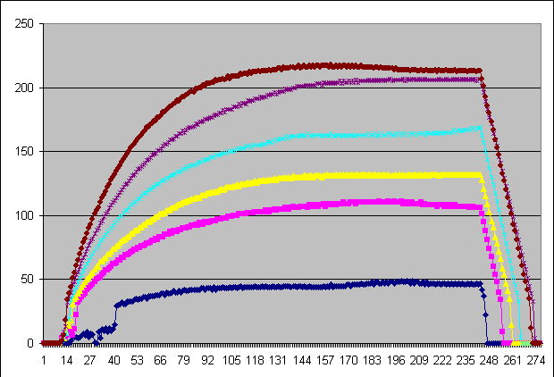
These are the signals from the tachometer, 6 complete start / stop cycles.
In this case, there is no PID, there is only a PHI controller set after power-up to a certain constant value, i.e. in fact, for each individual graph, the power is constant (but for each it is different).
The number of engine tachometer pulses is measured twice per second.
As you can see, the signal from the tachometer is quite stable (except for the first 20 seconds / 40 points on the lower blue graph, due to very low speeds) and it can not even be averaged.
Still quite interesting points:
1) after turning off the power supply to the engine, the speed drops almost linearly
2) the speed increase lasts about a minute, after which there may be a slight drawdown, this is especially noticeable on the lower graph, it is not entirely clear why this is connected, there may be small changes in the voltage in the mains.
And yes, it's at idle.
Another graph, as it was, control (blue graph) + speed from the tachometer (pink) 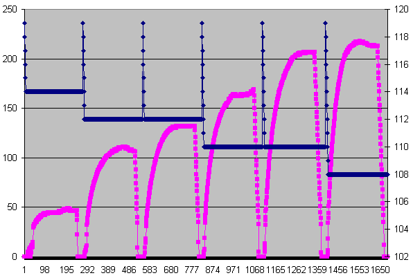
Here are all 6 cycles, the direction of rotation of the engine alternates, you can see the ratio of control and reaction to it. After power is applied, the control signal smoothly decreases from 120 to 114,112,110,108. It should be noted that the motor has a different torque depending on the direction of rotation, so with the same control value, different speeds are obtained!
Answer the question
In order to leave comments, you need to log in
I would move in the direction of taking control of the power developed on the engine and limiting the torque. Not a specialist in electric motor control, but he solved something similar for a hydraulic system (if I understood the task correctly). The presented turnover chart is not very interesting. It would be much more interesting to look at the current graph. I would move towards a cascaded pid controller where the internal circuit would be a current feedback controller set by a speed feedback controller - this will allow you to control the acceleration process while still being within the limit of the torque on the motor shaft . Something like that, I think. In general, think about what parameters of the system you can generally control, and read about cascades of pid controllers. As for theory, I advise articles oncontrolguru.com/table-of-contents from cover to cover ;) English, unfortunately...
PS Yes, and nothing prevents you from changing the settings of the pid controller on the fly, automatically, depending on the actual measured process parameters.
As it was such a task, I found easy approximate formulas for calculating the coefficients on the Internet, in which the coefficient values were calculated from graphical calculations plotted on the transfer characteristic graph of this system with an input shock of the maximum possible amplitude. Search the Internet, I don't remember where I found it now. After obtaining the values of the coefficients, the regulation did not work perfectly, but as soon as I slightly corrected the differential coefficient, the regulation became almost the most optimal
Didn't find what you were looking for?
Ask your questionAsk a Question
731 491 924 answers to any question