Answer the question
In order to leave comments, you need to log in
How to stabilize current/voltage from an unstable power supply?
There is a Chinese thermometer with an LCD indicator. I decided to turn it into an eternal one by connecting a 1 farad ionistr with a small solar battery module instead of batteries as a power supply. But here's the problem, the solar panel gives out, depending on the lighting, about 1.2-5 volts and a current from 1 to 50ma. A Chinese thermometer consumes 1.5 volts in general, and the current there is in microamps, if it grabs too much, it will hardly survive. I can’t get a zener diode and a stabilizer due to quarantine, radio stores are closed. How can one primitively limit the current / voltage from improvised means so that the thermometer does not snatch too much? In theory, the ionistr can refuel over 1.5v.
PS Available for analysis is a power supply from a computer, a video card, various resistors and LEDs, and a pair of diodes ...
Answer the question
In order to leave comments, you need to log in
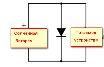
Nice to answer such a simple question! Well, firstly, they learned how to power simple devices with an LCD display from solar cells many years ago, these were desktop calculators. There were no ionistors then, they were fed directly, and in order to prevent excess voltage, a simple diode limiter was placed in parallel with the load.

The principle of its operation is that a voltage of about 0.55 ... 0.7 volts is fixed on the silicon diode in the forward direction. If we want to fix the voltage twice as much (like you have), then you need to turn on two silicon diodes in series - the limiting voltage will then increase to 1.1 ... 1.5 volts. As for the current, the diode absorbs all the current given by the battery, in excess of what is needed for the powered circuit and charging the ionistor (by the way, the presence of the ionistor connected in parallel with the diode does not change anything in the principle of operation of this circuit). Since the currents from the sun in such miniature devices are scanty, there is no danger for this limiter.
(By the way, this is why it seems to me that your estimate of the maximum current from a solar battery of 50 mA is greatly overestimated - about a hundred that way. 50 mA could be obtained from a battery not the size of a postage stamp, which is usually put in miniature devices, but with a palm, and even then under direct bright sun ... Nevertheless, microampere currents are usually enough to power such devices.)
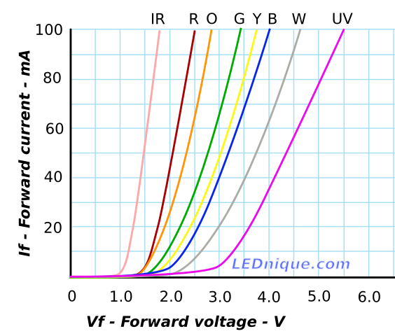
Instead of conventional silicon diodes, various LEDs can be used in this circuit. Here are their volt-ampere characteristics:

It can be seen from them that one infrared LED limits the forward voltage at a level of about 1.1 volts (i.e. it can replace a chain of two silicon ones), red and orange - about 1.5 volts, green - about 1.7 volts, and blue, ultraviolet (and white, by the way) - from 2.5 volts and above. Series connection, as with silicon, increases the limited voltage in proportion to the number of diodes included.
So, once again: you choose the voltage yourself, and don't let the current bother you until your solar battery exceeds the size of a matchbox.
Available for analysis is a power supply from a computer, a video card, various resistors and LEDs, and a pair of diodes ...Now about where to get them. Of course, you don't have to buy. Silicon diodes can be found on any electronic board with a probability of 99.9 ...%. You can solder an infrared LED from an old remote control from any household appliance. And other colored LEDs are also not in short supply in a home storage cabinet, they are full of any household appliance, starting from an electric kettle.
Well, according to the logic, the term must be powered from Akum, which is already charged by the solar panel
1. mikruha-voltage stabilizer for 1.5 volts.
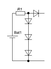
2. assemble a parametric voltage regulator circuit. because you have a small voltage instead of a zener diode, use three silicon diodes, it will give out exactly one and a half volts at the output.

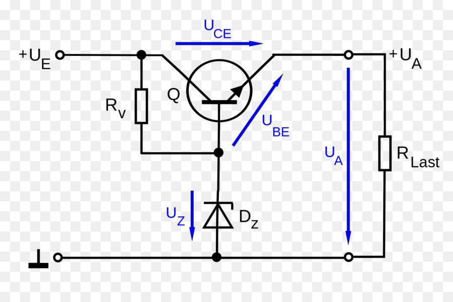
On a conventional diode, the drop is about 0.7 volts, you can turn on one or more in series, but then charging will only take place at a high voltage. The same effect, reducing the maximum voltage, can probably be achieved simply by covering part of the panel with an opaque material :). To stabilize, you can try this scheme:

Didn't find what you were looking for?
Ask your questionAsk a Question
731 491 924 answers to any question