Answer the question
In order to leave comments, you need to log in
How to properly connect 74hc595 to raspberry?
There was a problem. I connect these registers in a cascade to a raspberry. Four registers work properly. I solder the fifth or more to them, and a glitch occurs, in the same place. It is the second register that starts to get weird. I make the Q0 leg active, it activates two at once (Q0, Q1), I give the command to turn on Q1, but it is activated in fact on the Q2 leg, as a result, the signal is knocked down to one output on this register and because of this there are only 7 legs . If the fifth register is unsoldered, then everything works as before. The board has been cleaned a thousand times and covered with an electrical protective varnish, but it has already broken the whole head, can anyone come across this, what can it be, tell me? Or interference on the line? Capacitors where to shove or something else?
I connected it according to the principle as in this picture, only I have them in a cascade, the values \u200b\u200bof the resistors and the capacitor that are the same in the picture. The power supply from the raspberry is set to 3.3 volts (maybe they are not enough?)
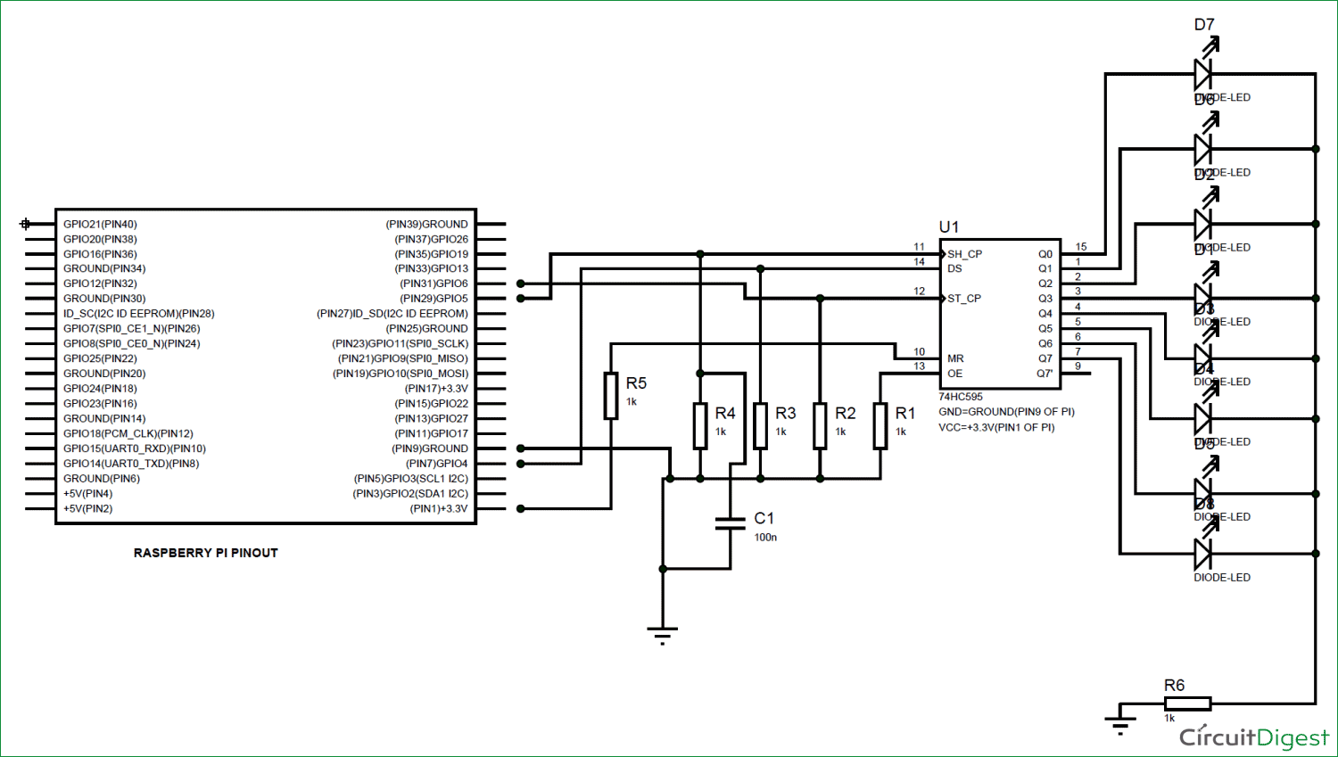
UPD. From the read datasheet it is not entirely clear whether there is a dependence in the operation of the register when powered by 3.3 volts and 5 volts. And how many miliamps at least each register needs. Now it turns out for the plus and minus of the power supply for 1k (at 3.3v) and these resistors are common to all registers, it's only 5 milliamps that they share with each other.
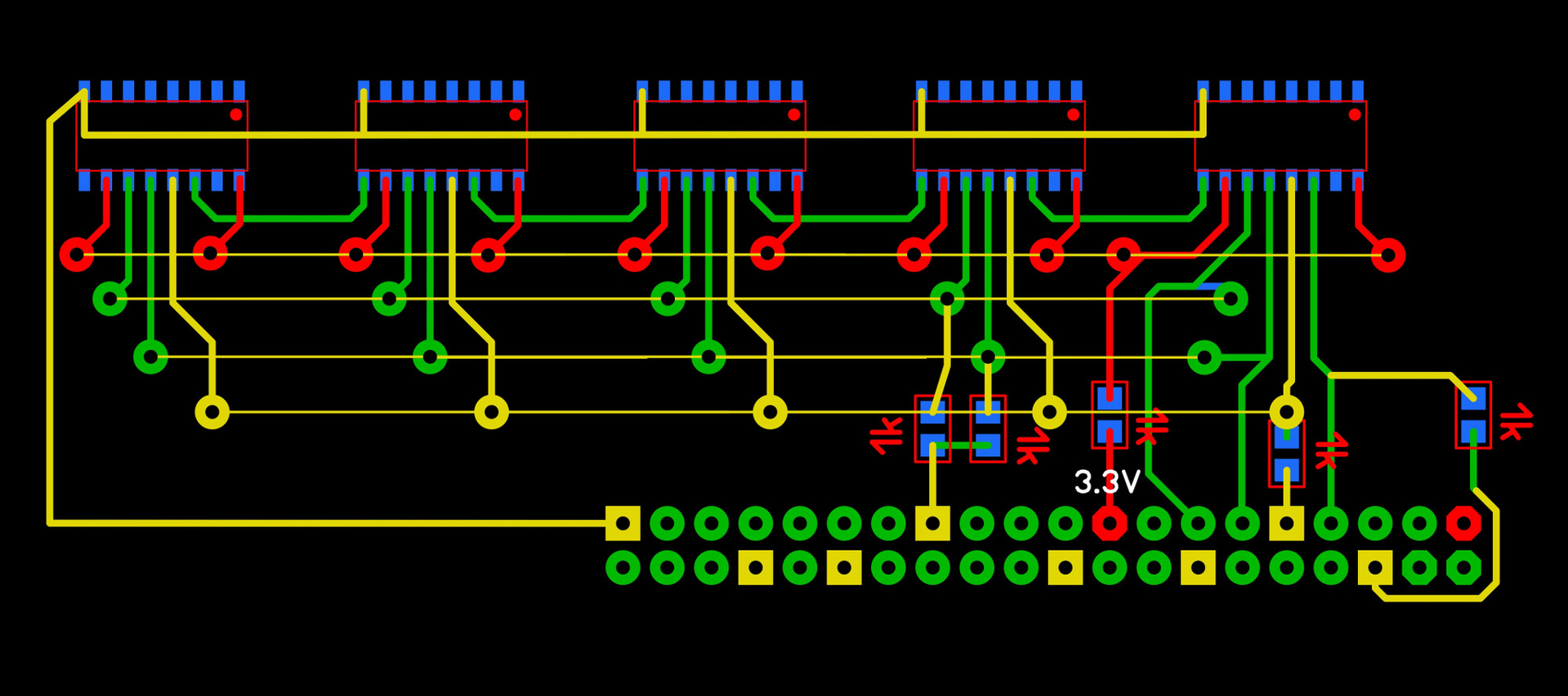
UPD. I am attaching a photo of the circuit in the form in which I have it now implemented!
Answer the question
In order to leave comments, you need to log in
I beg your pardon, gentlemen. In my amateurish view of the circuit, it is easy to guess that the resistances R2, R3 and R4 affect the already weak Raspberry current. I think it would not be bad to increase them to 1.5kΩ to reduce the current consumption of the GPIO. To the author: 5ma - your registers are not divided, but summed up among themselves. By number of registers
Didn't find what you were looking for?
Ask your questionAsk a Question
731 491 924 answers to any question