Answer the question
In order to leave comments, you need to log in
How to connect seven-segment indicators?
Hello ! I am currently working on an autopilot panel project for a flight simulator. I want to do something like this: I 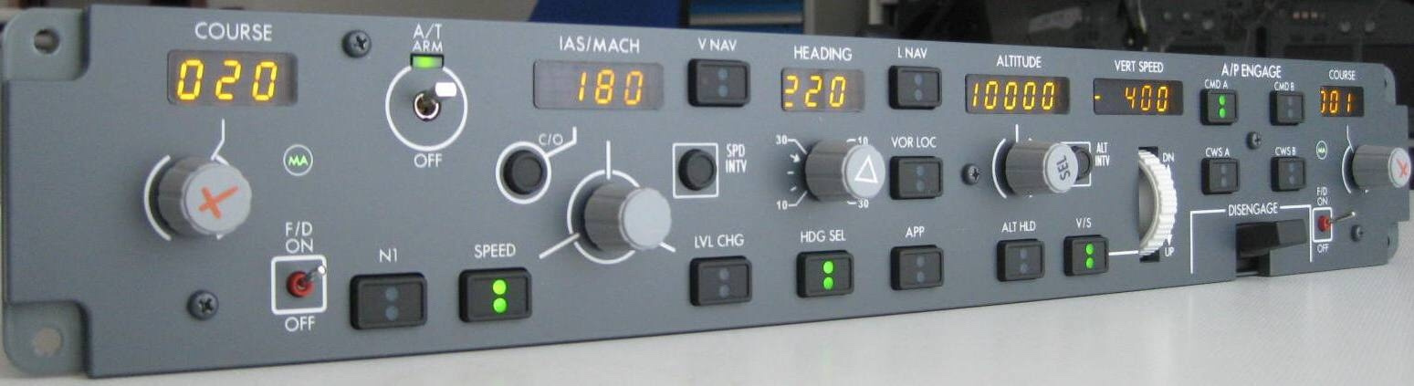
ordered 19 seven-segment indicators, but, for obvious reasons, I can’t connect everything to the microcontroller. I know about shift registers, but I don’t quite understand the principle of operation, the purpose of some pins. Can you clearly explain how they work, and how best to organize the connection of such a number of displays? Maybe some other shift registers, not 74HC595, or the correct combination of 74HC595?
Answer the question
In order to leave comments, you need to log in
I do not quite understand the principle of operation, the purpose of some pins
one register for each digit. they use 3 outputs data, strobe and record. Data output - connected in a chain (from the second register to the first from the first to the microcontroller). Strobe (Clock) - pulses - for each data bit change - each byte has 8 pulses (in parallel for all microcircuits). Recording (Latch) - a pulse to write the transmitted state to the outputs - one pulse to display the transmitted information (in parallel for all microcircuits).
Didn't find what you were looking for?
Ask your questionAsk a Question
731 491 924 answers to any question