Answer the question
In order to leave comments, you need to log in
How does a transistor regulate voltage in linear power supplies?
The transistor is current controlled. If its gain is 10, the collector voltage is 12V, and 5V 10mA is applied to its base, then the load will be 12V 100mA (we will neglect the base current). Is everything right? Then how does a transistor regulate the voltage in linear power supplies? Understanding what fundamental things I lack to realize this?
Below is the simplest circuit of a linear PSU. The stabilized voltage divided by the potentiometer is applied to the base, why on earth does it produce the same voltage at the emitter, and not the collector voltage?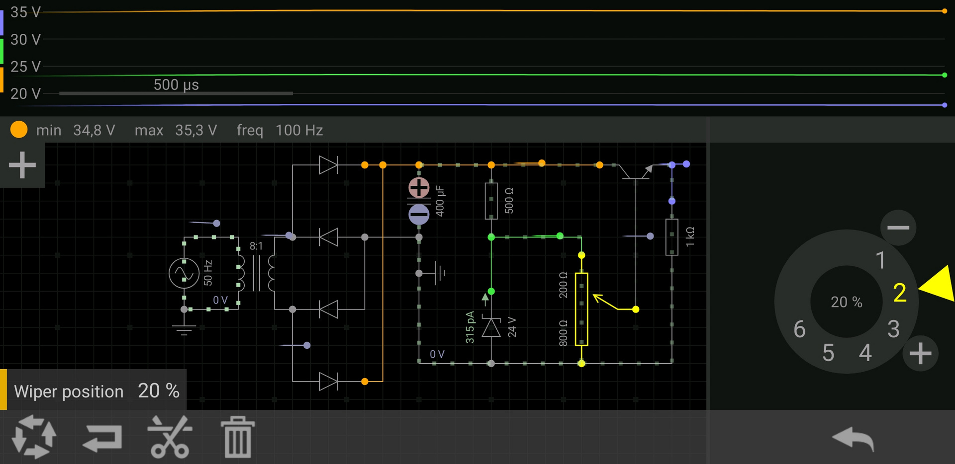
Answer the question
In order to leave comments, you need to log in
I opened the transistor, the current flowed, the voltage increased - the transistor closed, the voltage decreased - the transistor opened again.
FSE is very simple (if you don’t go into details)
the greater the base current,
the greater the collector current
in this circuit, the zener diode holds the given voltage,
(current flows through the base-emitter junction)
with a known resistance = transistor base current,
on the collector (collector junction -emitter happens the same thing, but the currents are orders of magnitude higher.
this is the basis of electronics, and if you don’t understand this .... (no words = not yours)
PS
then the load will be 12V minus the drop at the transistor junction (≈ 0, 7c),
and the current is limited only by the parameters of the transistor (well, the supply current
read about emitter followers, it is this switching circuit in such power supplies:
- high input impedance, which allows the use of low-current zener diodes
- the gain is about 1, which is why it is called a follower
- low output impedance, which is important for power supplies.
according to the scheme:
the voltage at the emitter will be slightly less than at the base, if the zener diode is 12V, the output will be slightly less than 12V.
In general, with different switching schemes (common base, common emitter, common collector), the operation of the transistor is very different, respectively, and the current / voltage formulas are different.
"Elementary, Watson" (c). Let's say you want to change the voltage on a light bulb. To do this, you need to connect a variable resistor in series with it:
(Ignore the ammeter in this circuit - it just measures the current). We turn the variable knob - the voltage on the light bulb changes (its brightness also changes), since part of the voltage is taken by the resistor, and the greater its resistance, the greater the part taken. They brought the resistor all the way to the right - its resistance became zero, respectively, the full voltage of the battery was applied to the light bulb.
A circuit of two (or more) resistors in series is called a "voltage divider" because its supply voltage is divided between them in proportion to their resistances.
So, the trick is that a transistor is the same variable resistor, only it is controlled not by a twist knob, but by the current supplied to the base (this is bipolar) or the voltage supplied to the gate (this is field). The rest of the linear power supply circuit, which we will not consider here, serves only to control the resistance of this transistor to maintain the desired voltage at the output (well, or another parameter - for example, the desired current, then it will be a current stabilizer).
Didn't find what you were looking for?
Ask your questionAsk a Question
731 491 924 answers to any question