Answer the question
In order to leave comments, you need to log in
Choosing a relay or transistor switch for Arduino?
Hello!
I assembled a temperature monitoring device based on Arduino UNO and GSM SIEMENS TC35 Module.
The device measures the temperature, takes this data and sends it via SMS to the desired number once every 24 hours.
And everything seems to be fine, but there is one “but”. In order for the “system” to start working, you need to manually turn on the GSM SIEMENS TC35 Module by pressing a button on it, and only after that it works and allows you to send SMS.
While it brought to the external button on the case. But I want the device to work without external interference.
I want to send a "on" signal and close the contacts of the "red button" when the Arduino starts.
How to do this programmatically is clear, but here it is necessary to implement the hardware (see RED Button in the diagram ).
As I understand it, I need to put a relay or a transistor switch. Tell me, please, what to put?
Advise brands, models, links to schemes. Anything you consider useful in solving the problem.
The control voltage is 5 volts.
The voltage at the contacts of the "red button" is up to 3-4 volts.
Currents 30-40 mA
Thanks in advance.
Answer the question
In order to leave comments, you need to log in
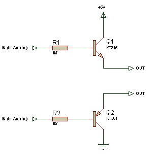
Look, the button is connected to the plus or to the ground.
Based on this, you will make a choice towards npn or pnp transistor.
Transistor - in your case, absolutely any bipolar. Even the domestic KT315 or KT361 will do. Or 2N2222.
Connection - a resistor to the base 1-10KΩ
It may not work, due to the voltage drop at the junction, you need to try.
PS Write in a personal, we'll figure it out
I tried to find a circuit for the board, but I didn’t find it, but I think that the signal from the button goes directly to the controller, and then it’s possible to do without a transistor switch or relay and connect the arduino output. But it is better to clarify the logical levels in the controller. Although, judging by your circuit, the power supply of the module is 3.3v, and you supply 5v and everything works, I would venture to suggest that the logic of the module controller is tolerant of 5v ttl. Or maybe you should not power the 5v module, is there 3.3 nearby?
And where is the guarantee that the "red button" controls the "plus or ground"? In addition, there, with a certain probability, there are anti-bounce chains. It is necessary either to roll out the TC35 circuit here, or, for peace of mind, use any 5V relay. And the relay is connected through the key, according to the upper post scheme, by paralleling the relay with a diode to protect the transistor from induction currents.
Yes, there are probably anti-bounce circuits if there is no software debounce, but I think that they still won’t interfere with the signal from the arduino output. To determine what the button controls, it is enough to use the tester and check what is on the other side of the button. Since there is only one button, it is unlikely that there is a dynamic poll or an analog chain.
For cases where it is not clear where what voltage is and whether it exists at all, it is easier, but a little more expensive, to use a solid state relay.
This is a semiconductor device. The input is an LED. The LED shines on the transitor, transistors, triacs, etc. and thus opens it. The input is galvanically "isolated" from the output, the breakdown voltage is usually > 1000 V.
KR293KP2A 60 V 320 mA, approximately 50 r
www.platan.ru/pdf/electrotech_198.pdf
www.platan.ru/cgi-bin/qweryv.pl/0w48286 .html
Didn't find what you were looking for?
Ask your questionAsk a Question
731 491 924 answers to any question