Answer the question
In order to leave comments, you need to log in
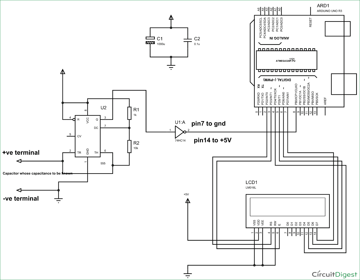
Can't understand the project diagram for capacitance measurements?

I don't understand electronics at all, so I just need to connect it on an arduino breadboard. I use the following components:
555 timer chip;
Schmitt trigger chip 74LS14 or NOT elements;
Arduino Uno board;
LCD display 16x2;
capacitors 100 nF and 1000 uF;
resistors 1 kOhm (2 pcs.) and 10 kOhm (1 pc.);
Answer the question
In order to leave comments, you need to log in
Everything is quite simple.
Long lines are wires.
All sorts of things are radio elements, the designation of which is easily googled.
Big things are large elements, all their conclusions are numbered, as in reality, if you look at them.
Take and collect the designer.
If anything, Google, in response to the request "how to read radio circuits", gives out both short articles and videos for 10 minutes.
Didn't find what you were looking for?
Ask your questionAsk a Question
731 491 924 answers to any question