Answer the question
In order to leave comments, you need to log in
Why is the marginal gain -1?
Why do logic gates leave a large voltage increment in the forbidden zone?
Answer the question
In order to leave comments, you need to log in
I didn't mean the allowable noise levels between the output of one valve and the input of another, I meant the input and output of one valve described by the transfer characteristic.Apparently, you do not understand that for many different logical elements, and for the only one, this is the same thing . The point here is the strict standardization of the type of HRP for all elements of one logical series. Once upon a time, in the old reference books, they drew the type of PX separately for inverters, separately for AND-NOT, separately for OR-NOT, etc., but then, when it dawned that the difference in their style is so insignificant that it can be ignored, this stopped doing.
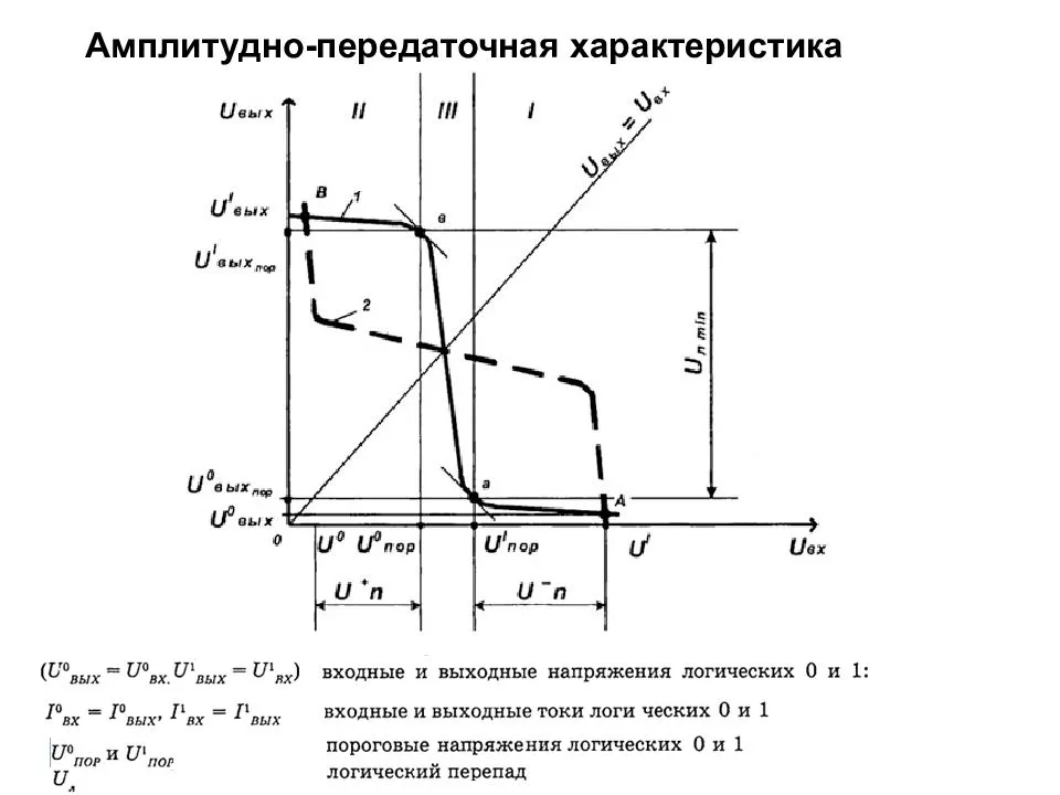
sort of understood: if the change in voltage at the output is faster than at the input. then such a gap should be located in the forbidden zone, because any interference will be multiplied many times.All that is available to you when designing a logic element is the manipulation of the inflection voltages of the HV for the upper and lower switches so that the resulting HV is approximately symmetrical. However, there are other methods to increase the resistance of logic to interference - for example, the introduction of different thresholds for switching from 0 to 1 and from 1 to 0 (this is the so-called "Schmitt trigger".) Here's how it looks: On the
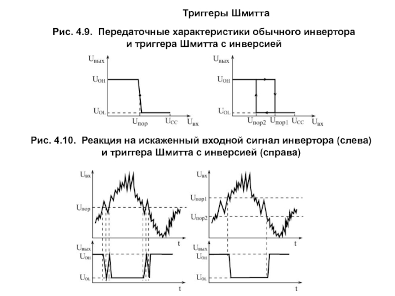 left -- The RH of a conventional logical element, and accordingly, the type of signal with the interference passed to the output, on the right - the same for the element with the trigger RH, the interference does not pass to the output.
 Didn't find what you were looking for?
Ask your questionAsk a Question
731 491 924 answers to any question