N
N
nuclear_kote2021-02-09 00:19:42
Electronics
nuclear_kote, 2021-02-09 00:19:42

What is the problem with the schema?

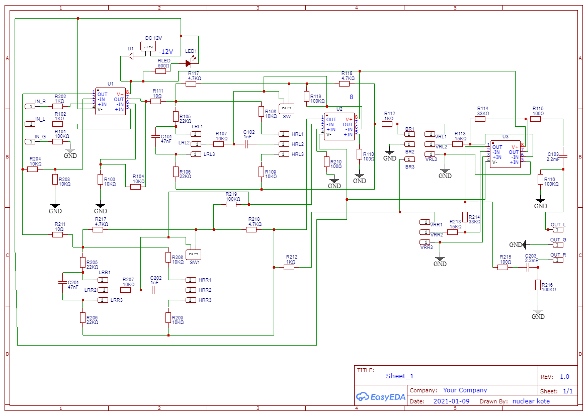
I'm trying to make a preamplifier.
I found this scheme on the Internet: I
6021a86907941987254728.jpeg
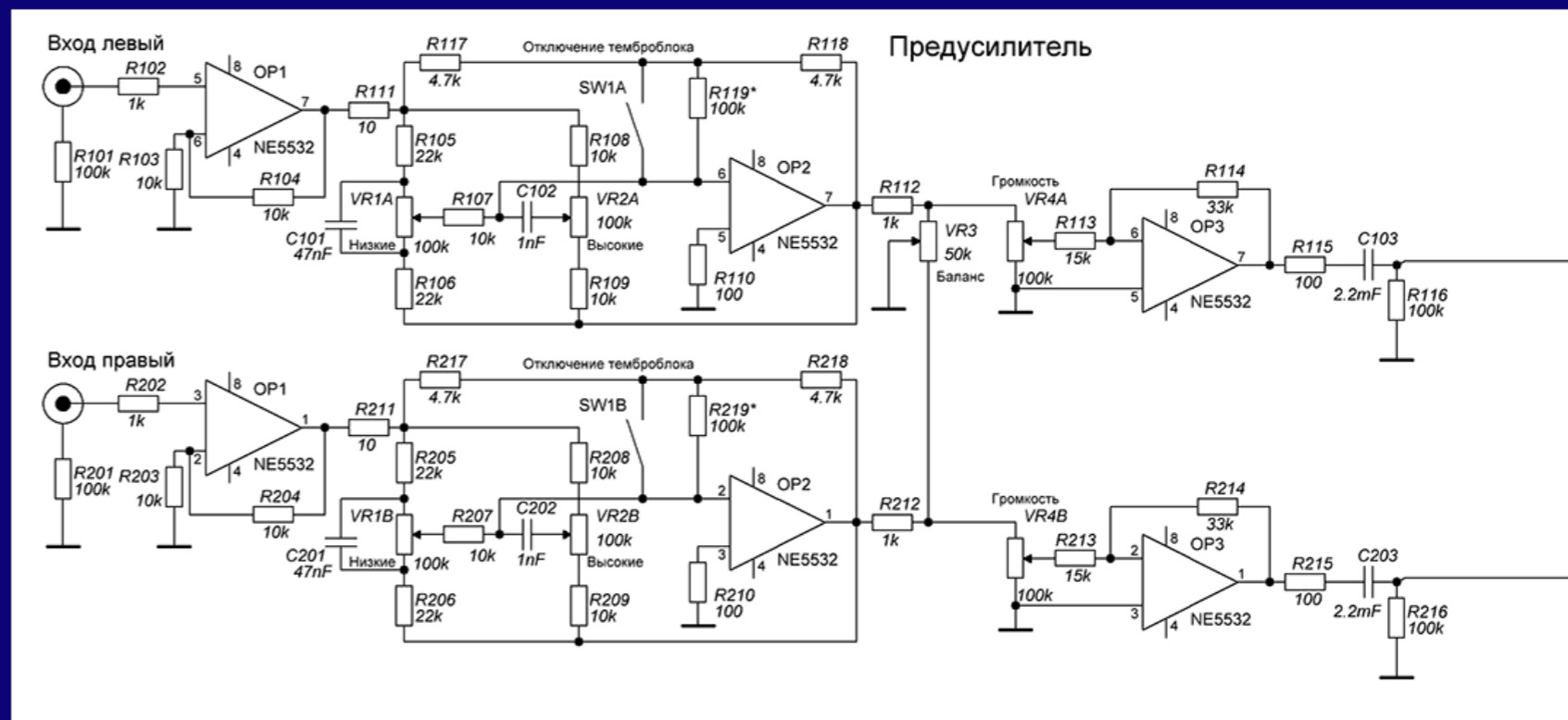
redrawn it in easyeda:
6021a8e462ec2152700153.png
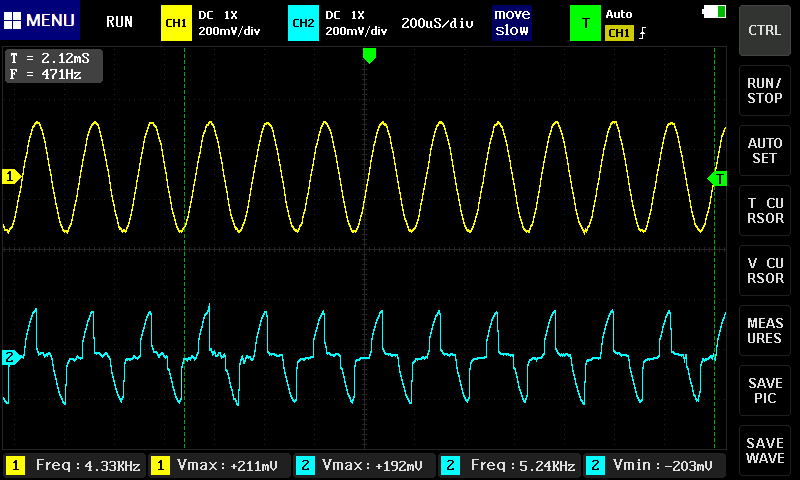
If I connect 1 channel, it doesn't matter which one is right or left and I turn the balance towards this channel, everything works fine, but if I connect both channels, then on the 1st and 7th outputs of the 1st OI the following picture appears (yellow represents the input, blue represents the 1st or 7th output)
6021aa371fee6043446468.png

OI using TL072 Chinese. Factory made board

What could be the problem?

Answer the question

In order to leave comments, you need to log in

2 answer(s)
V
VT100, 2021-02-09
@nuclear_kote

They threw R201 out of the circuit, but the value of R101 was not reduced

Rather - in the original scheme, there is a jamb of drawing and you need to look at the original board, if there is a drawing. As Denis noted , the OU1 inputs turned out to be hanging in the air (for direct current), but this is not true. 2 resistors of 100 kΩ must be connected to the left terminals of R101 and R102, and IN_G must be grounded. Now - it turned out something like a difference amplifier for the input signals of the channels.
If necessary, "close" the DC inputs, as Fox Jovovich writes .
Diode D1 can't do that. But there is a question with power supply: do you use a unipolar 12V supply or a bipolar ± 12V supply? If the first - it is necessary to make a "virtual" land.

V
vanyamba-electronics, 2021-02-09
@vanyamba-electronics

Try to unbalance.

Didn't find what you were looking for?

Ask your question

Ask a Question

731 491 924 answers to any question