Answer the question
In order to leave comments, you need to log in
What inductance (choke) to choose for the Linear Laboratory power supply at the output of the diode bridge (0-30V max. 10A max. 160watt 50 * 2Hz)?
Essence of the question:
I dream of collecting a laboratory power supply in my free time (it is very necessary to experiment well, or to charge batteries, for example).
I remember from childhood that grandfathers said that the purest source that has an LC filter.
Remembering a little background, I know that hefty chokes used to be wound, since it was easier and cheaper to make them than to find large capacitors.
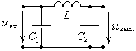
But still, I really wanted to implement in my self-made block, a kind of "P - shaped" or "L - shaped" LC filter.
The transformer will be used TS-160-3, the windings will be switched from bi-polar (0-15V to 5A) to single-polar ( 0-15V max. 10A or 0-30V max. 5A ).
I understand that through this throttle (?) will flowcurrent up to 10A and the power of the inductor will be up to 160W. Capacitors 50V 10000uF (k50-18 domestic)
will be used .
The question is, is there such a ready-made choke, what does it look like, or how should this choke look, or what parameters should it have?
<<< Attention! >>> Please note that the power supply will be adjustable, the transformer at 50Hz, respectively, at the output of the full diode bridge will already be 100Hz, linear and with current protection against overload and short circuit. The LS filter will be right after the diode bridge. Capacitors Soviet K50-18 for 50 volts 10,000 microfarads. Immediately after the filter there will be a "two linear choke" if, of course, it is necessary . Voltage and current stabilization circuit and other logic will be after the filter
Answer the question
In order to leave comments, you need to log in
Roughly speaking, you have a ripple frequency of 100 hertz (there are more), look at the throttle in the welding inverter
, it is half a fist, yes, the currents there are higher (30 times), but the frequency that it filters is 200-400 times higher, that is, the efficiency from a choke at 100 hertz smaller than a fist should not be expected
in the case of a linear converter, filters that make sense to put
1) a 600 volt varistor in parallel with the 220 winding
2) a thermistor in series with the 220 winding
3) ceramic capacitors in parallel with each diode - when closing, the diode creates an RF interference that will be amplified by a transformer and sent back to the 220 network or (and) will go further, and high-capacity aluminum electrolytes do not dampen RF interference at all
4) purely symbolically, you can make some kind of choke of 10 turns from RF interference coming from the network 220 and in front of it is the same symbolic film capacitor for 1 microfarad and damping RF interference.
5) large electrolytes
6) no more than 1 microfarad film capacitors after the linear stabilizer will block the remaining ripples that the stabilizer will make during operation
, and the bonus is a 12-volt power supply shutdown in which no additional filters are provided (1,2,3,4) from network
turned out from the 15th time
Sergey, what decision did you end up with?
I have a similar task - after a powerful 24V transformer there is a diode bridge, I wanted to put a step-down converter on the XL4016 (with Ali) to adjust the output voltage and limit the current, but I need a filter between them (24V and ~ 6A). I myself am not a big specialist, I did not find a simple solution by googling. Your branch is just in the subject, but there is no ending.
Write, please, what did you end up with.
Didn't find what you were looking for?
Ask your questionAsk a Question
731 491 924 answers to any question