Answer the question
In order to leave comments, you need to log in
How to understand the contacts of a bistable relay?
Dear electronics engineers, please help me figure out the relay contacts.
There is an NCR NRL708A-WX2-1B-12-D relay ( like this ).
It has three legs on one side and two on the other.
The side with two legs is understandable - this is a load.
But how to manage three contacts? I always thought that in bistable relays there are two control contacts: we give an impulse, the load turns on, we give it again - it turns off.
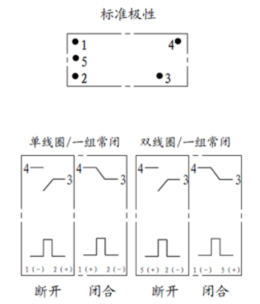
The datasheet has this picture with Chinese inscriptions: 
So, how does it work anyway?
And the second question. This is a normally closed relay. Is it suitable for lighting control from two points or is it better to take with normally open? The button will be connected to the 12V DC line, the bulbs - 220V AC.
Here I don't quite understand this configuration either. Norm. lock, normal open - what's the difference if the relay is bistable?
Please help me figure this out. I have not found a wiring diagram for this (or similar) relay.
Thank you.
UPD: Will I be able to turn on and then turn off the light bulb connected to the relay load with one button with two consecutive presses? If not, what relay should be used for this?
Answer the question
In order to leave comments, you need to log in
It is called a bistable relay because both states are stable and the relay remains in its current state until a pulse is applied to the control contacts. It does not have normally closed or normally open contacts.
The drawings are read like this: "If you apply a minus to pin 1 and a plus to pin 2, then the relay will go into an open state." Similarly for the rest of the drawings.
The way you want this relay is not turned on, it needs an additional control circuit.
Control from two places can be done without a relay, using not switches, but two-position switches. But I have not seen them on the wall.
The easiest way is to use factory impulse relays, they are available both in DIN version and in an installation box. This is exactly what you see on the Internet.
Well, according to the scheme, everything is clear.
If on 1 - on 2 + - open
If on 1 + on 2 - - closed
If on 5 + on 2 - - open
If on 1 - on 5 + - closed.
You can if this button sends the right signals to the relay. In the above case, you need to look at what kind of button and how + and - are "routed" in it. The relay is not responsible for this - the button is responsible for this.
Normally closed - isn't it when the contacts are closed when the load is removed? Well, then I wouldn't use it - something goes wrong and your light is always on.
PS nifiga not a circuit engineer - so, common sense and analysis ...
Didn't find what you were looking for?
Ask your questionAsk a Question
731 491 924 answers to any question