Answer the question
In order to leave comments, you need to log in
How to compensate for back EMF?
Good day!
Assembled a controller for an electromechanical lock.
But it periodically freezes. As far as I understand, due to the large back EMF.
There are both relays and reverse diodes on the relay to compensate for both relay EMF and induced from the lock.
The lock is good, the return line pulls straight. Food is supplied separately.
At first, it hung every time after opening. Installed compensating diodes. Now it hangs much less often, but every 2-3 days it still happens.
And how to get rid of? Can you install a varistor? Or someone please advise ..
PS
A piece of the circuit is something like this
Answer the question
In order to leave comments, you need to log in
Do you have two relays and a lock there? Why two relays? Why not 3 or 4?
Output the arduino output to the optocoupler. The optocoupler immediately turns on a powerful relay that switches your electromagnet.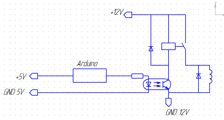
You're right about optocoupling!
I’m not Vanga, but something tells me that your arduino is powered by a pulsed DC-DC lower, you can put a film conder and ceramics at its output, this will at least somehow improve the situation, I would also like to clarify that the lower is powered by 12V of the same what and the castle is recorded? So in this case, before optocoupling, sculpt the capacitor again that way (12V supply × 0.1A operating current of the lock = 1.2V * A × 100uF / Wat = 120uF, taking into account that it is Chinese then ×2 = 240uF)
Ideally, do not take into account operating current and starting current, which is about 10-100 times more than the working current, that is, you only need 2400 microfarads from the capacity of the power supply for the lock.
Then, you put a shunt diode, but you didn’t put a series diode.
And now let's also remember that you have a common switching power supply, and when you use Chinese power supplies, it is advisable to take their power 1.5 times more than calculated.
Now let's think about what is happening with you, the frequency of the switching power supply is approximately 100 kHz, and the frequency of the arduino is 16-8 MHz, that is, the starting current of your lock, and the RF interference through the diodes has already been acting for several operations, and the MK can simply get lost what command it is executing, not to mention the fact that it may be incorrect to read or write something. For this reason, I recommend that you open the datasheet for your diodes, look at their response time (the maximum current rise rate) and put a ceramic capacitor in parallel with the Castle to suppress interference.
Another trick is a soft starter, like a thermal fuse, only works in the opposite direction.
At the output of the 5V step-down, put a suppressor, also known as a generator, also known as a protective diode.
In the code, wait at least 1/4 sec after turning the relay on and off without performing any operations (especially calculations and writing to RAM), see how the watchdog timer is configured.
Look like that's it. Good luck.
Do you need to explain that you have either a voltage drop or an RF high-voltage interference, or will you figure it out yourself?
Didn't find what you were looking for?
Ask your questionAsk a Question
731 491 924 answers to any question