Answer the question
In order to leave comments, you need to log in
100 ohm resistor between 24V and 0V?
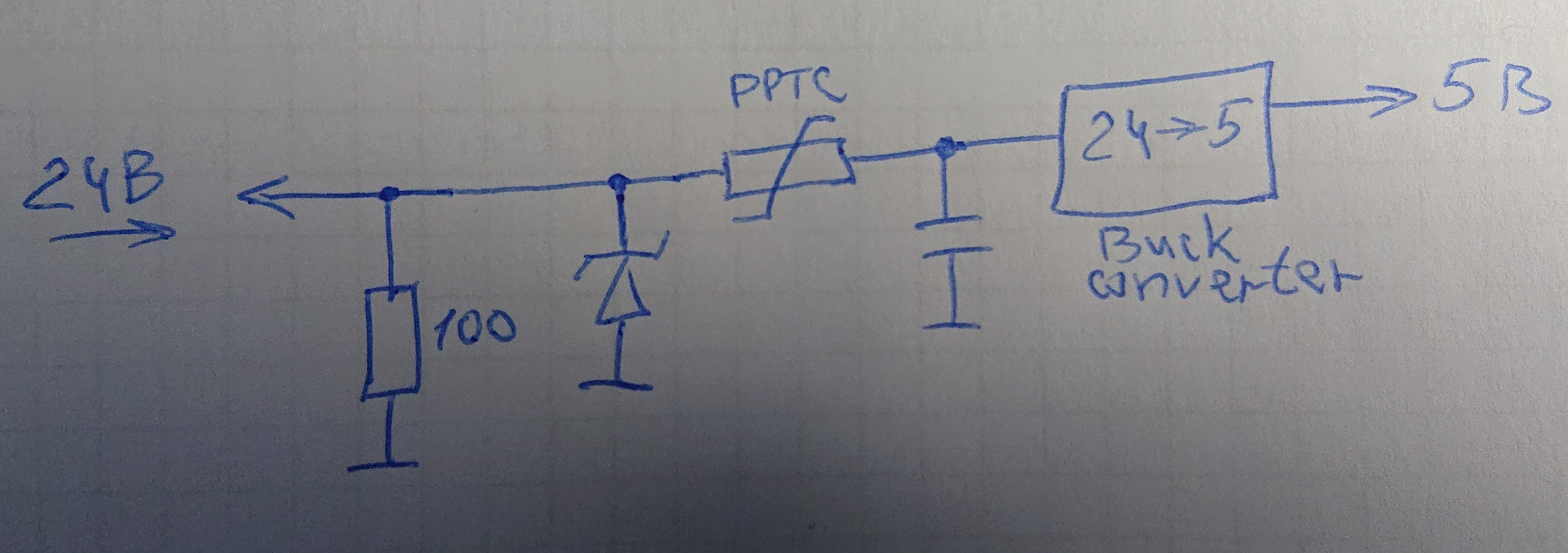
I studied the power circuit on the board of a purchased active USB hub. Powered by an external power supply unit 24V. Then there is a converter to 5V and then these 5 V diverge across the board. I am attaching the diagram.
Question - why is there a 100-ohm resistor directly parallel to the input? Its size is 0805, why hasn't it burned out yet?
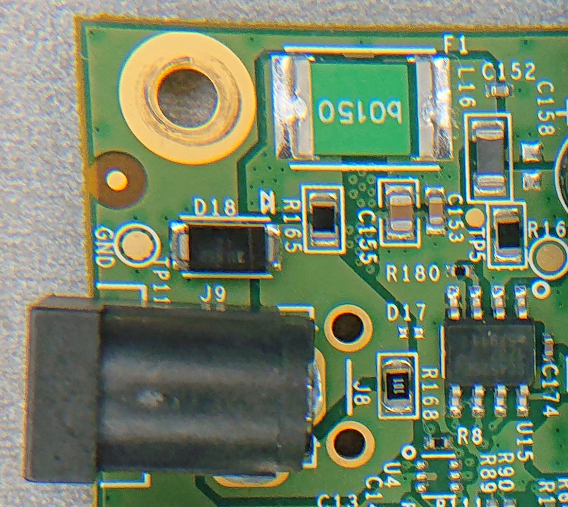
UPD: Added a photo of the board. The resistor in question is R168. One of its outputs through a 0 Ohm resistor R165 goes to the power circuit, its other output rings with the ground (the photo shows that it is connected to the side output of the input connector - a standard coaxial power connector 2.5x5.5). The microcircuit in the photo is SC4525ESETRT.
Answer the question
In order to leave comments, you need to log in
It seems to me that it is necessary to check the connection of the third contact of the connector used to switch "battery-network":
https://static.chipdip.ru/lib/507/DOC001507919.pdf
Discharging the input capacitor when the power is turned off.
So this is not a 100 ohm resistor, but someone intended some garbage. Attach a photo of the patient.
Or at least it's turned on wrong.
Didn't find what you were looking for?
Ask your questionAsk a Question
731 491 924 answers to any question